
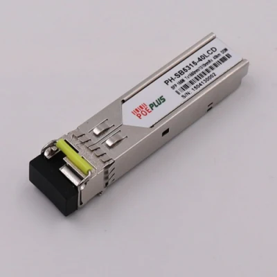
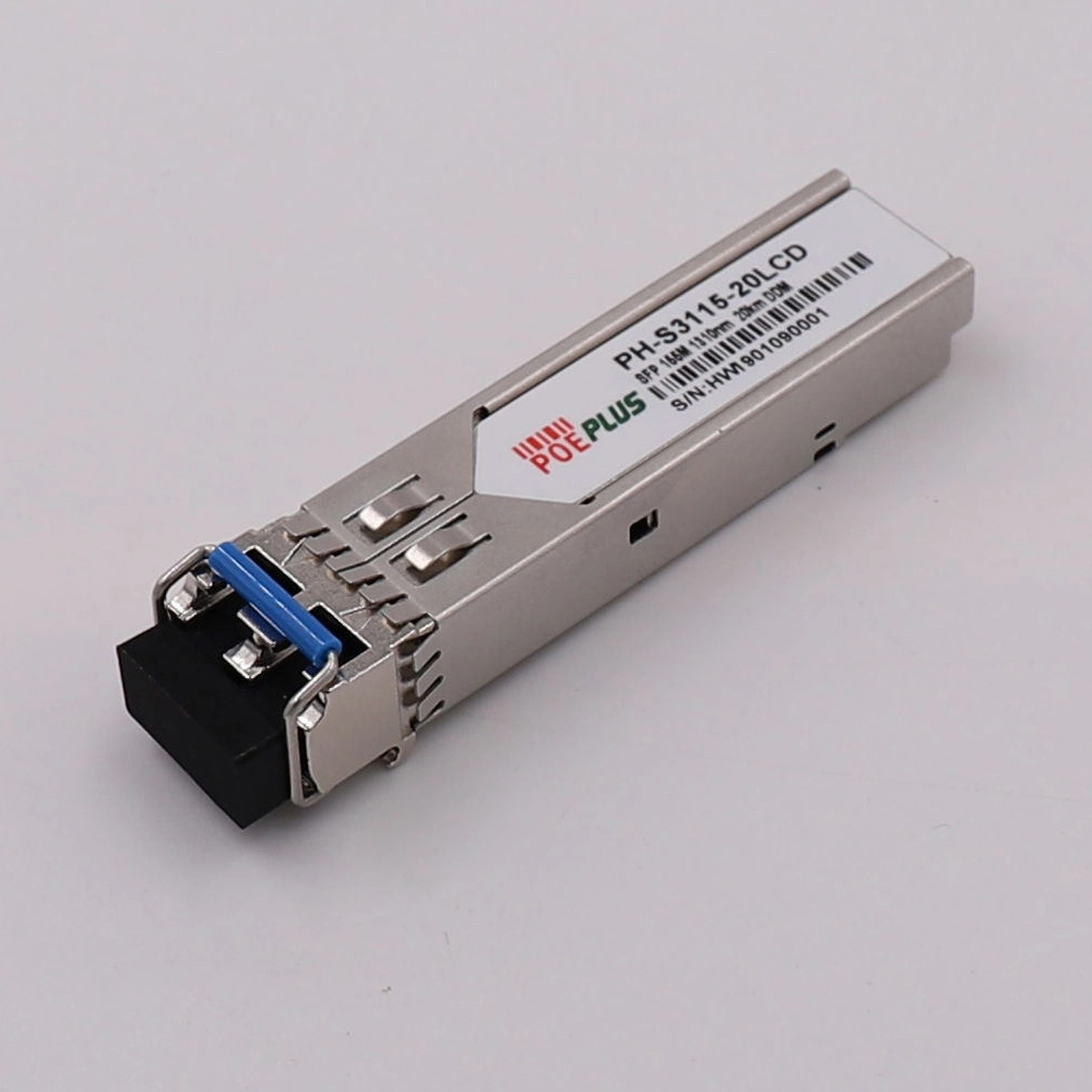
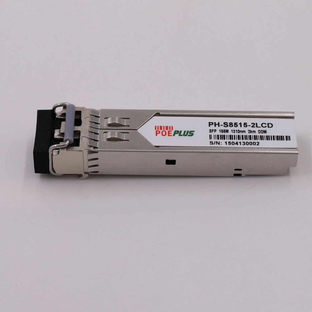
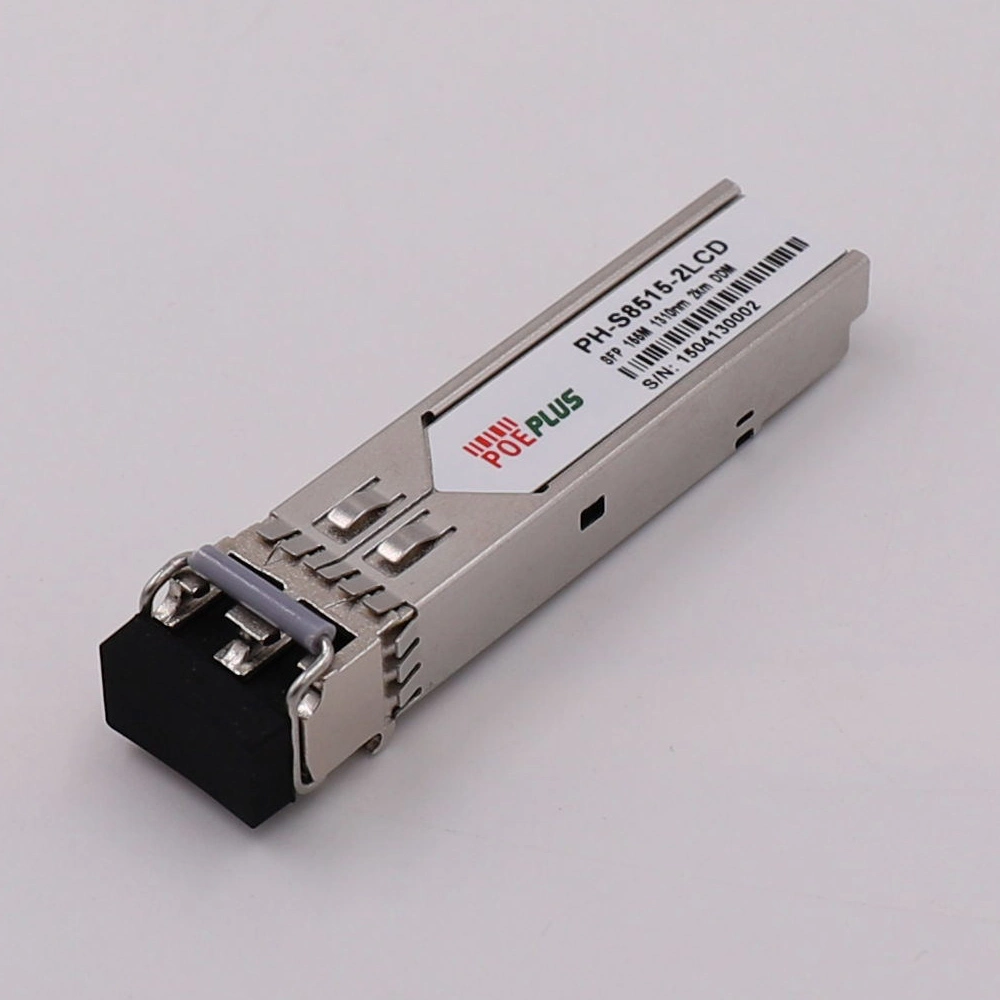
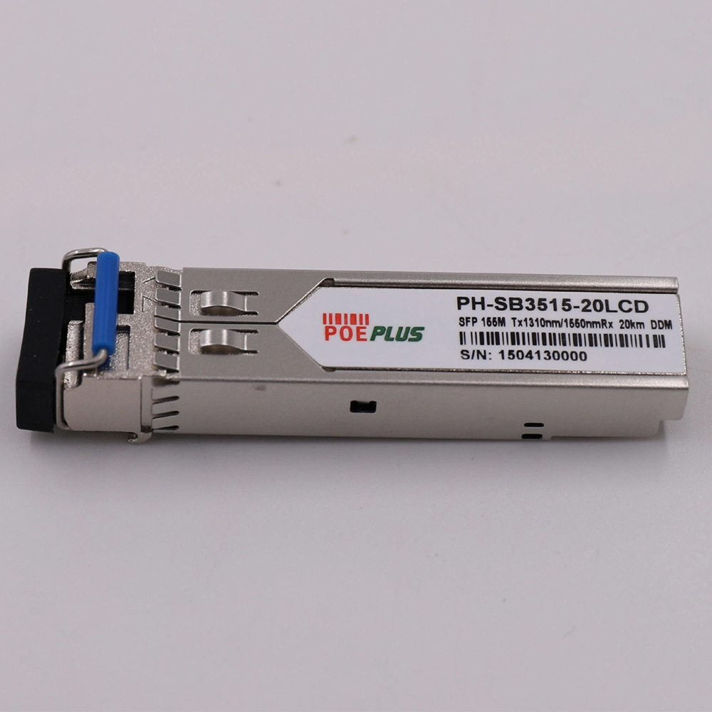
155m SFP Module Optical Transceiver (PHF
Features Up to 155Mbps data links Hot-pluggable SFP footprint 850nm Oxide VCSEL laser transmitter Duplex LC connector Ro;
Basic Info.
| Model NO. | PHF-8524-1LS |
| Rate | 155Mbps |
| Transport Package | Unit Packge Size: 374*232*82mm |
| Specification | CE/EMC, CE/LVD, FCC Certification |
| Trademark | PHYNAM |
| Origin | Dongguan Guangdong China |
| HS Code | 8471802000 |
| Production Capacity | 1000PCS Per Week |
Product Description
FeaturesUp to 155Mbps data links
Hot-pluggable SFP footprint
850nm Oxide VCSEL laser transmitter
Duplex LC connector
RoHS Compliant and Lead-Free
Up to 20km on single fiber
Metal enclosure, for lower EMI
Single power supply 3.3V
Low power dissipation
Commercial operating temperature range: 0°C to 70°C
APPLICATIONS
155Mbps 100Base-SX Ethernet
SDH
The PHF-8524-1LS Small Form Factor Pluggable (SFP) transceivers are compatible with the Small Form Factor Pluggable Multi-Sourcing Agreement (MSA). They are simultaneously compatible with Gigabit Ethernet as specified in IEEE Std 802.3 and Fibre Channel FC- PI-2 Rev. 7.0. They are RoHS compliant and lead-free per Directive 2002/95/EC
I. Pin Descriptions
| Pin | Symbol | Name/Description | Ref. |
| 1 | VEET | Transmitter Ground (Common with Receiver Ground) | 1 |
| 2 | TFAULT | Transmitter Fault. Not supported. | |
| 3 | TDIS | Transmitter Disable. Laser output disabled on high or open. | 2 |
| 4 | MOD_DEF(2) | Module Definition 2. Data line for Serial ID. | 3 |
| 5 | MOD_DEF(1) | Module Definition 1. Clock line for Serial ID. | 3 |
| 6 | MOD_DEF(0) | Module Definition 0. Grounded within the module. | 3 |
| 7 | Rate Select | No connection required | |
| 8 | LOS | Loss of Signal indication. Logic 0 indicates normal operation. | 4 |
| 9 | VEER | Receiver Ground (Common with Transmitter Ground) | 1 |
| 10 | VEER | Receiver Ground (Common with Transmitter Ground) | 1 |
| 11 | VEER | Receiver Ground (Common with Transmitter Ground) | 1 |
| 12 | RD- | Receiver Inverted DATA out. AC Coupled | |
| 13 | RD+ | Receiver Non-inverted DATA out. AC Coupled | |
| 14 | VEER | Receiver Ground (Common with Transmitter Ground) | 1 |
| 15 | VCCR | Receiver Power Supply | |
| 16 | VCCT | Transmitter Power Supply | |
| 17 | VEET | Transmitter Ground (Common with Receiver Ground) | 1 |
| 18 | TD+ | Transmitter Non-Inverted DATA in. AC Coupled. | |
| 19 | TD- | Transmitter Inverted DATA in. AC Coupled. | |
| 20 | VEET | Transmitter Ground (Common with Receiver Ground) | 1 |
1. Circuit ground is internally isolated from chassis ground.
2. Laser output disabled on TDIS >2.0V or open, enabled on TDIS <0.8V.
3. Should be pulled up with 4.7k - 10kohms on host board to a voltage between 2.0V and 3.6V.
MOD_DEF(0) pulls line low to indicate module is plugged in.
4. LOS is open collector output. Should be pulled up with 4.7k - 10kohms on host board to a voltage
between 2.0V and 3.6V. Logic 0 indicates normal operation; logic 1 indicates loss of signal.
II. Absolute Maximum Ratings
| Parameter | Symbol | Min | Typ | Max | Unit | Ref. |
| Maximum Supply Voltage | Vcc | -0.5 | 4.0 | V | ||
| Storage Temperature | TS | -40 | 85 | °C | ||
| Case Operating Temperature | TA | 0 | 70 | °C | ||
| Relative Humidity | RH | 0 | 85 | % | 1 |
Notes:
1. Non condensing.
III. Electrical Characteristics (TA = 0 to 70 °C, VCC = 3.0 to 3.6 Volts)
| Parameter | Symbol | Min | Typ | Max | Unit | Ref. |
| Supply Voltage | Vcc | 3.0 | 3.6 | V | ||
| Supply Current | Icc | 150 | 240 | mA | ||
| Transmitter | ||||||
| Input differential impedance | Rin | 100 | Ω | 2 | ||
| Single ended data input swing | Vin,pp | 250 | 1200 | mV | 3 | |
| Transmit Disable Voltage | VD | 2 | Vcc | V | 4 | |
| Transmit Enable Voltage | VEN | Vee | Vee+ 0.8 | V | ||
| Receiver | ||||||
| Single ended data output swing | Vout,pp | 250 | 450 | 550 | mV | 5 |
| Data output rise time | tr | 175 | ps | 6 | ||
| Data output fall time | tf | 175 | ps | 6 | ||
| Mask Margin | 45% | |||||
| LOS Fault | VLOS fault | 2 | VccHOST | V | 7 | |
| LOS Normal | VLOS norm | Vee | Vee+0.5 | V | 7 | |
| Power Supply Rejection | PSR | 100 | mVpp | 8 | ||
| Deterministic Jitter Contribution | RX Δ DJ | 51.7 | ps | 9 | ||
| Total Jitter Contribution | RX Δ TJ | <65 | 122.4 | ps | 10 | |
Notes:
2. Connected directly to TX data input pins. AC coupling from pins into laser driver IC.
3. We recommend <600mV for best EMI performance.
4. Or open circuit.
5. Into 100 ohms differential termination.
6. 20 - 80 %
7. LOS is an open collector output. Should be pulled up with 4.7k - 10k ohms on the host board. Normal operation is logic 0; loss of signal is logic 1. Maximum pull-up voltage is 5.5V.
8. Receiver sensitivity is compliant with power supply sinusoidal modulation of 20 Hz to 1.5 MHz up to specified value applied through the recommended power supply filtering network.
9. Typical peak-to-peak jitter (=6*RMS width of Jitter).
10. Measured with DJ-free data input signal. In actual application, output DJ will be the sum of input DJ and Δ DJ.
IV. Optical Characteristics (TOP = 0 to 70 °C, VCC = 3. 00 to 3.60 Volts)
| Parameter | Symbol | Min | Typ | Max | Unit | Ref |
| Transmitter | ||||||
| Output Opt. Pwr: 50 or 62.5 MMF | POUT | -9 | -3 | dBm | 1 | |
| Optical Wavelength | λ | 830 | 860 | nm | ||
| Spectral Width | σ | 0.85 | nm | |||
| Optical Modulation Amplitude @ 1.0625 Gbps | OMA | 156 | μW | 2 | ||
| Optical Rise/Fall Time | tr/ tf | 100 | 150 | ps | 3 | |
| Relative Intensity Noise | RIN | -120 | dB/Hz | |||
| Deterministic Jitter Contribution | TX Δ DJ | 20 | 56.5 | ps | 4 | |
| Total Jitter Contribution | TX Δ TJ | <65 | 119 | ps | 5 | |
| Extinction Ratio @ 1.25 Gbps | ER | 9 | dB | |||
| Mask Margin | 45% | |||||
| Receiver | ||||||
| Receiver Sensitivity = 1.0625 Gbps | RxSENS | -20 | dBm | 6 | ||
| Receiver Sensitivity = 1.25 Gbps | RxSENS | -20 | dBm | 7 | ||
| Stressed RX sens. =1.0625 Gbps | 0.055 | mW | 8 | |||
| Stressed RX sens. =1.25 Gbps | -13.5 | dBm | 9 | |||
| Average Receiver Power | RxMAX | 0 | dBm | |||
| Receiver Elec. 3 dB cutoff freq. | 1500 | MHz | ||||
| Optical Center Wavelength | λC | 770 | 860 | nm | ||
| Optical Return Loss | 12 | dB | ||||
| LOS De-Assert | LOSD | -20 | dBm | |||
| LOS Assert | LOSA | -30 | dBm | |||
| LOS Hysteresis | 0.5 | dB | ||||
Notes:
1. Class 1 Laser Safety per FDA/CDRH, IEC, and EN60825-1 laser safety standards.
2. Equivalent extinction ratio specification for Fibre Channel. Allows smaller ER at higher average power.
3. Unfiltered, 20-80%. Complies with FC 1x and 2x eye mask when filtered.
4. Measured with DJ-free data input signal. In actual application, output DJ will be the sum of input DJ and Δ DJ.
5. If measured with TJ-free data input signal. In actual application, output TJ will be given by:
6. Specifications are for 50 micro-meter or 62.5 micro-meter fiber
7. As measured with 9dB extinction ratio.
8. Measured with conformance signals defined in FC-PI-2 Rev. 7.0 specifications.
9. Measured with conformance signals defined in IEEE 802.3 specifications.
V. General Specifications
| Parameter | Symbol | Min | Typ | Max | Units | Ref. |
| Data Rate | BR | 1.062 | Gbps | 1 | ||
| 1.25 | ||||||
| Bit Error Rate | BER | 10-12 | ||||
| Fiber Length on 50/125μm MMF | L | 550 300 | m | 2 | ||
| Fiber Length on 62.5/125μm MMF | L | 300 150 | m | 2 |
Notes:
1. Gigabit Ethernet and 1x, Fibre Channel compatible, per IEEE 802.3 and FC-PI-2 Rev. 7.0
respectively.
2. At 1.0625 Gb/s Fibre Channel and 1.25 Gb/s Gigabit Ethernet data rates.
VI. Environmental Specifications
PHF-8524-1LS 850nm SFP transceivers have a commercial operating temperature range from 0°C to +70°C case temperature.
| Parameter | Symbol | Min | Typ | Max | Units | Ref. |
| Case Operating Temperature | Top | 0 | 70 | °C | ||
| Storage Temperature | Tsto | -40 | 85 | °C |
You may also like

Send inquiry
Send now